Data Processing
Quick Start Guide
This guide helps users become familiar with the monoDrive Real-to-Virtual data processing pipeline. The software uses several Docker images developed at monoDrive to process Real-to-Virtual data into data products and Unreal Engine levels usable in the monoDrive Simulator.
Pre-requisites
Processing Pipeline Installation
Users of the Real-to-Virtual software will have access to the monoDrive Real-to-Virtual deployment repository. This repo contains all software for processing real-to-virtual data into assets for us in Unreal Engine and the monoDrive Simulator.
Setup
Before building Docker images, the monoDrive AWS secret for authentication must be copied to your installation location:
- Copy file secrets file provided by monoDrive to the
etc/aws_secret_template.txt
Build
The repository provides a build script for creating the necessary Docker images. Run build script to create docker images and pull down configure assets:
$ ./build.sh
A new directory called config/ containing a copy of all config assets that
have been pulled down from their respective repositories. The config/
directory contains files which contain configuration parameters to tune for
individual Real-to-Virtual data collections. Note that these configs will not be
overwritten by the build script unless you pass the --overwrite-config flag.
Calibrating LiDAR Position
Though the default values from the original data collection should be sufficient for processing data, to better improve the lidar alignment, the LiDAR and camera registration tool can be used to apply slight offsets. Accurately registering the camera and LiDAR can lead to better cloud classification and more accurate dynamic actor detection.
The registration tool is provided as part of the monoDrive Real-to-Virtual software suite. This Python script allows the user to view the current calibration and easily provide minor offset values. To use the tool:
$ conda activate monodrive-r2v
(monodrive-r2v) $ python ./cloud_camera_registration.py -s \
    --data /path/to/data/collection/kitti \
    --show-intensity \
    --lidar_pos_offset 0.0 0.0 0.0 \
    --lidar_angle_offset 0.0 0.0 0.0
In this example, we are showing the intensity of the LiDAR mapped to a Jet colormap. The initial alignment can be seen in the following picture:
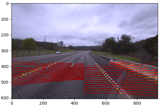
By providing slight offsets to correct for the angle of the LiDAR, we can align the high intensity points with the road markers:
(monodrive-r2v) $ python ./cloud_camera_registration.py -s \
    --data /path/to/data/collection/kitti \
    --show-intensity \
    --lidar_pos_offset 0.0 0.15 0.0 \
    --lidar_angle_offset -0.5 0.0 0.0
Here the angle offsets are in degrees and the position offsets are in centimeters. The resulting image shows perfectly aligned overlay of intensity onto the road markers:

Once the values have been determined, place them in the
config/sensor_offset.json file for use in the pipeline.
Calibrating the GNSS Position
Similar to calibrating the offsets between the LiDAR and the camera, a calibration can be applied to the LiDAR and GNSS in order to improve the fidelity of the final point clouds and meshes. The LiDAR and GNSS calibration tool is provided with the Real-to-Virtual distribution and can be used like:
$ conda activate monodrive-r2v
(monodrive-r2v) $ python ./lidar_gnss_calibration.py \
    --data /path/to/data/kitti \
    --gnss_pos_offset 0.0 0.0 0.0 \
    --gnss_angle_offset 0.0 0.0 0.0 \
This command should bring up a window to allow you to view the point cloud's current registration with no offsets. Notice the line (representing the location of the data collection vehicle) has several discontinuities.
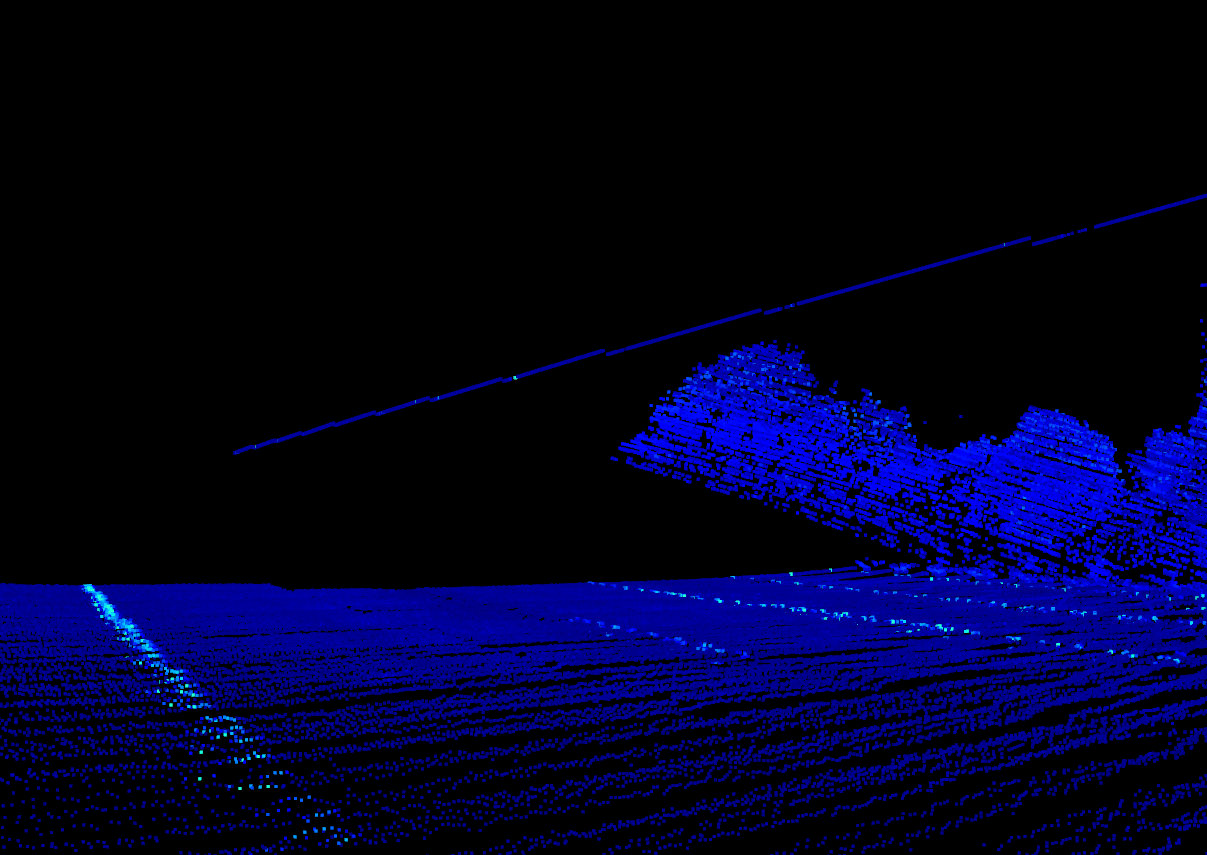
The discontinuities in the image above can be corrected by applying the following offsets:
(monodrive-r2v) $ python ./lidar_gnss_calibration.py \
    --data /path/to/data/kitti \
    --gnss_pos_offset 0.0 0.0 0.0 \
    --gnss_angle_offset -0.5 0.0 0.5 \
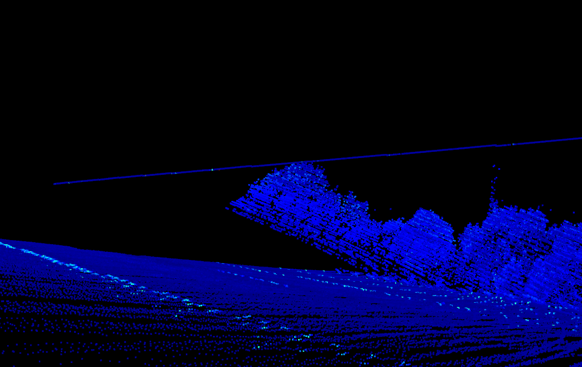
The position offsets are in centimeters and the angle offsets are in degrees. The resulting cloud now looks more correct:
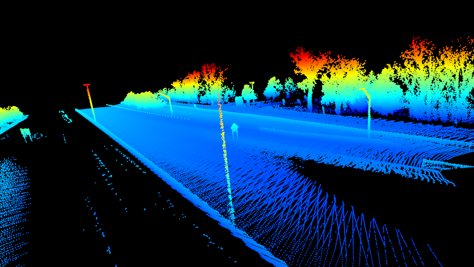
When applied to the entire stitched point cloud (used for mesh creation), the objects in the cloud become more apparent:
Once the values have been determined, place them in the
config/sensor_offset.json file for use in the pipeline.
Running the Pipeline
With the calibration completed and the values entered into the
config/sensor_offset.json the pipeline can be easily run:
$ run_pipeline.sh --workspace /path/to/data/collection