Data Processing
Quick Start Guide
This guide helps users become familiar with the monoDrive Real-to-Virtual data processing pipeline. The software uses several Docker images developed at monoDrive to process Real-to-Virtual data into data products and Unreal Engine levels usable in the monoDrive Simulator.
Pre-requisites
Processing Pipeline Installation
Users of the Real-to-Virtual software will have access to the monoDrive Real-to-Virtual deployment. These binary Docker images and configuration files contain all software for processing real-to-virtual data into assets for use in Unreal Engine and the monoDrive Simulator.
To install, navigate to the provided directory with Docker images and installation scripts and run:
$ ./install.sh --deployment-dir .
Calibrating LiDAR Position
Though the default values from the original data collection should be sufficient for processing data, to better improve the lidar alignment, the LiDAR and camera registration tool can be used to apply slight offsets. Accurately registering the camera and LiDAR can lead to better cloud classification and more accurate dynamic actor detection.
The registration tool is provided as part of the monoDrive Real-to-Virtual software suite. This Docker image allows the user to view the current calibration and easily provide minor offset values. To use the tool:
$ ./run_pipeline.sh --workspace /path/to/data_collection \
    --lidar-camera-calibration \
    --frame 100
--lidar-camera-calibrationtells the script to run the calibration tool.--frameis the frame in the data collection to view.
The tool uses the senor_offsets.json file in the config directory in the
deployment to apply offsets to the LiDAR rotation and translation. Change the
values in this file for lidar_pos_offset (meters in x, y, and z directions)
and lidar_angle_offset (degrees in the roll, pitch, and yaw) until the
LiDAR and camera are properly aligned. An example of JSON file can be seen here:
{
    "lidar_pos_offset": [0.0, 0.0, 0.0],
    "lidar_angle_offset": [0.0, 0.0, 0.0],
    "gnss_pos_offset": [0.0, 0.0, 0.0],
    "gnss_angle_offset": [0.0, 0.0, 0.0]
}
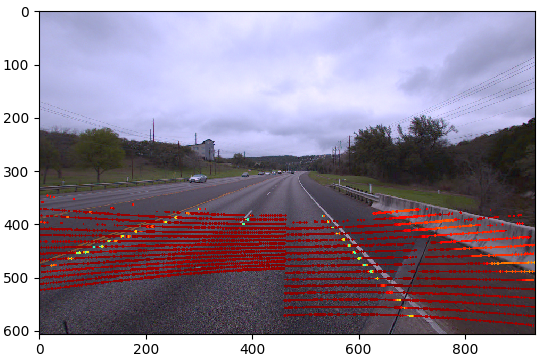
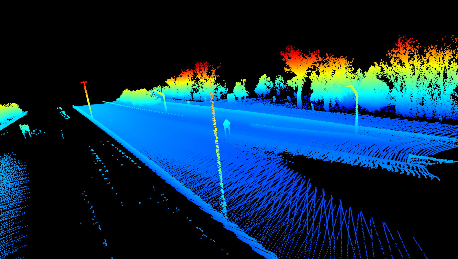
In the example below, initial alignment showing the intensity of the LiDAR mapped to a Jet colormap can be seen projected onto the image data:
By providing slight offsets to correct for the angle of the LiDAR, we can align the high intensity points with the road markers:
{
    "lidar_pos_offset": [0.0, 0.20, -0.06],
    "lidar_angle_offset": [-0.3, -0.15, 0.0],
    "gnss_pos_offset": [0.0, 0.0, 0.0],
    "gnss_angle_offset": [0.0, 0.0, 0.0]
}
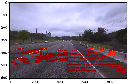
Here the angle offsets are in degrees and the position offsets are in centimeters. The resulting image shows perfectly aligned overlay of intensity onto the road markers:
Once the values have been determined, place update them in the
config/sensor_offset.json file for use in the pipeline.
Calibrating the GNSS Position
Similar to calibrating the offsets between the LiDAR and the camera, a calibration can be applied to the LiDAR and GNSS in order to improve the fidelity of the final point clouds and meshes. The LiDAR and GNSS calibration tool is provided with the Real-to-Virtual distribution and can be used like:
$ ./run_pipeline.sh --workspace /path/to/data_collection \
    --lidar-gnss-calibration \
    --frame 100 \
    --number-of-frames 20
--lidar-gnss-calibrationtells the script to run the calibration tool.--frameis the frame in the data where the calibration will begin.--number-of-framesis the total number of frames to use when stitching clouds.
The tool uses the senor_offsets.json file in the config directory in the
deployment to apply offsets to the GNSS rotation and translation. Change the
values in this file for gnss_pos_offset (meters in x, y, and z directions)
and gnss_angle_offset (degrees in the roll, pitch, and yaw):
{
    "lidar_pos_offset": [0.0, 0.0, 0.0],
    "lidar_angle_offset": [0.0, 0.0, 0.0],
    "gnss_pos_offset": [0.0, 0.0, 0.0],
    "gnss_angle_offset": [0.0, 0.0, 0.0]
}
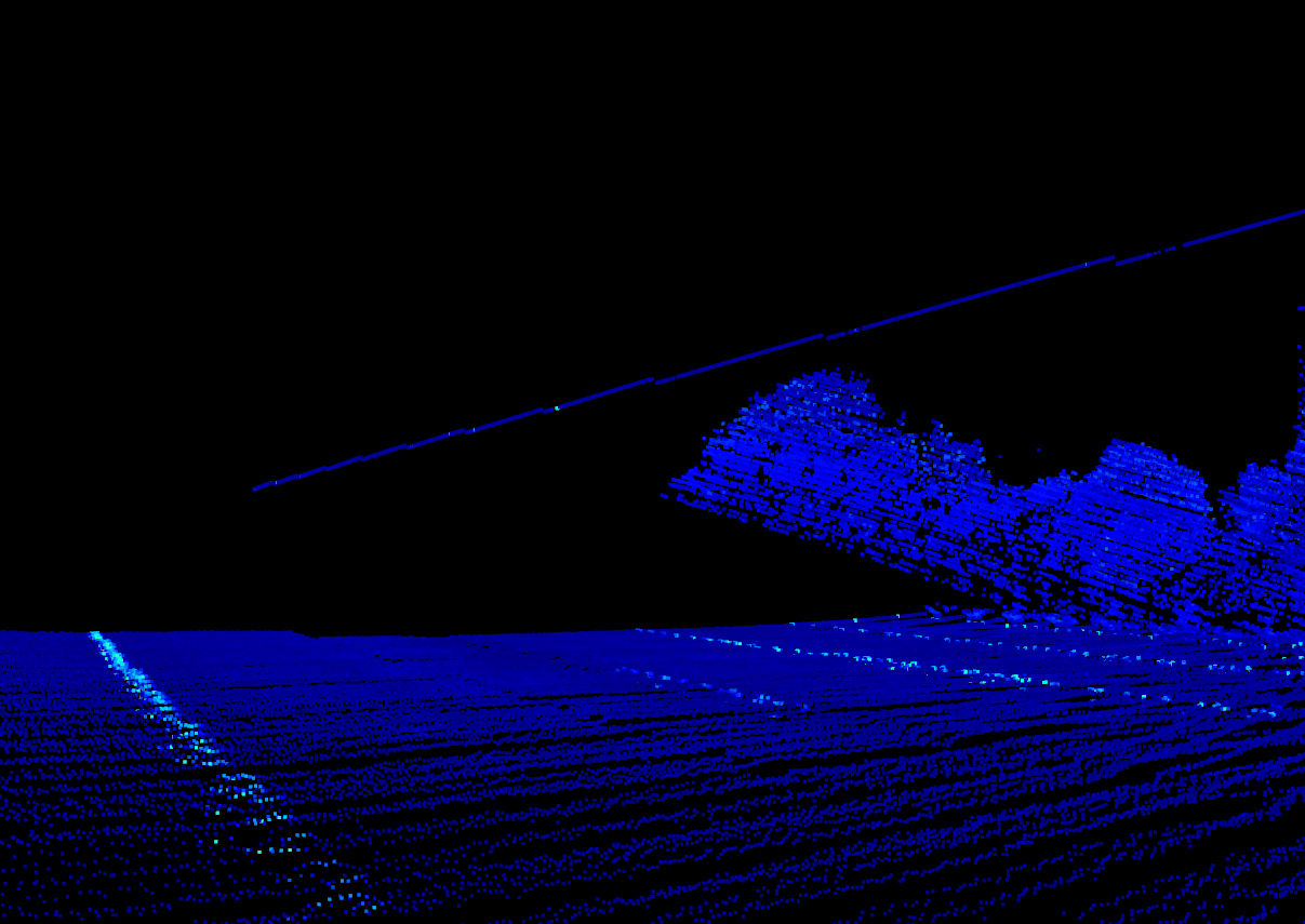
Using the default values of 0 in the sensor_offset.json will bring up a
window to allow you to view the point cloud's current registration with no
offsets. Notice the line (representing the location of the data collection
vehicle) has several discontinuities.
The discontinuities in the image above can be corrected by applying the following offsets:
{
    "lidar_pos_offset": [0.0, 0.0, 0.0],
    "lidar_angle_offset": [0.0, 0.0, 0.0],
    "gnss_pos_offset": [0.02, -0.02, 0.01],
    "gnss_angle_offset": [-0.5, 0.0, 0.5]
}
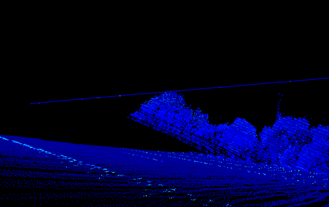
The position offsets are in meters and the angle offsets are in degrees. The resulting cloud now looks more correct:
When applied to the entire stitched point cloud (used for mesh creation), the objects in the cloud become more apparent:
Once the values have been determined, place update them in the
config/sensor_offset.json file for use in the pipeline.
Calibrating Texture Mapping
After a data set has been run through the pipeline, texture mapping can be
updated if necessary by using the Texture Mapping Alignment Tool
to better align the GNSS and camera. This tool allows the user to see
a portion of the rough texture mapped mesh rotate the offset between the
GNSS and camera in order to align features. This tool will allow users to
calibrate the rotation_offset value in the
config/texture_mapping_config.json file.
To use the tool:
$ ./run_pipeline.sh --workspace /path/to/data_collection \
    --texture-mapping-alignment
This will bring up the GUI window for manipulating the alignment. The mesh and texture mapping are controlled through the mouse and keyboard:
Right mouse+w/s/a/d: Control the camera view of the mesh4/5: Rotate texture alignment in yaw6/7: Rotate texture alignment in roll8/9: Rotate texture alignment in pitchn: Move forward one step in the pose graphm: Move backward 10 steps in the pose graph
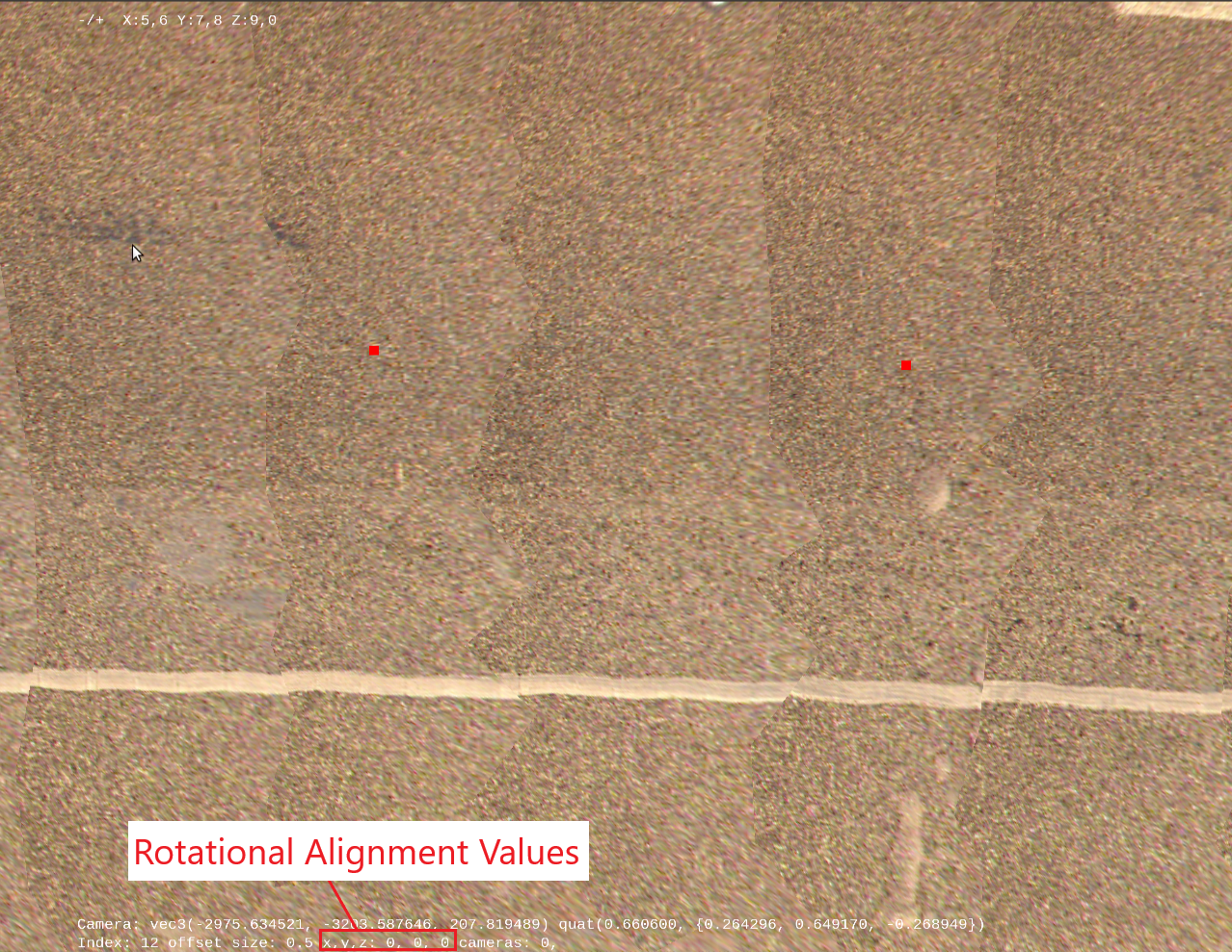
The below image shows texture mapping with the original alignment, the alignment values for yaw, roll, and pitch can be seen at the bottom. Notice the lane edge markers are slightly skewed:
By manipulating the texture mapping alignment, a better alignment can be found as shown below. Notice the straight lane edge markers:
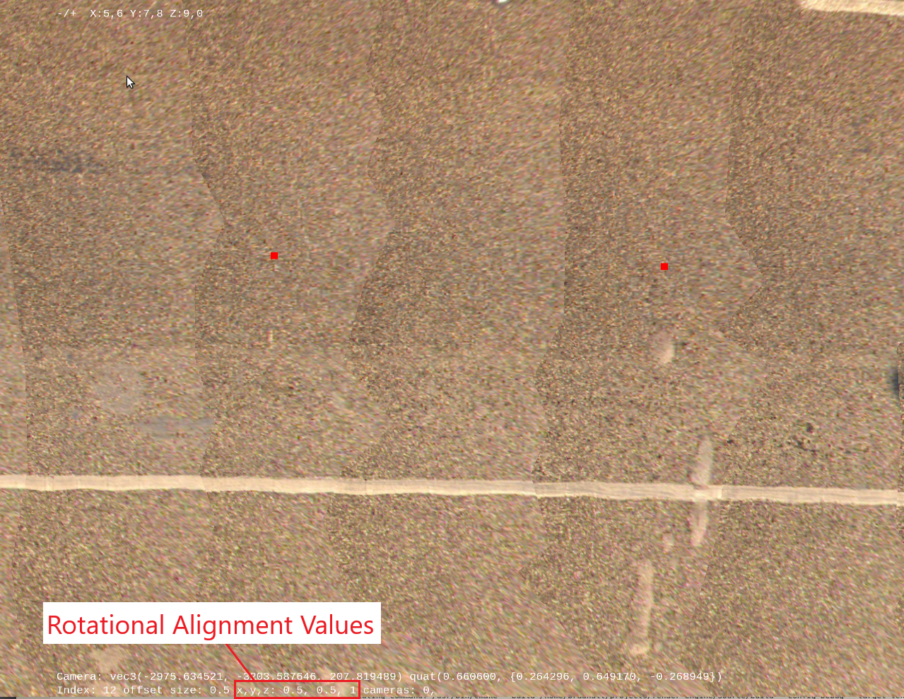
Once the alignment is found, the values printed on the screen can be copied into
the texture_mapping_config.json in the rotation_offset. The re-running
the pipeline with these values installed will yield a slightly better texture
mapping:
{
    "ppm": 80,
    "max_resolution": 2048,
    "cameras": [4, 0, 1],
    "spherical_cameras": [],
    "start_index": 0,
    "end_index": 50000,
    "num_boundary_triangle_layers": 0,
    "pose_graph": "cloud/gnss_cam_path.txt",
    "rotation_offset": {
        "x": 0.5,
        "y": 0.5,
        "z": 1.0
    },
    "models": [
        {
            "mesh_filename": "000175_road_cloud.obj",
            "max_projection_distance": 2000.0,
            "min_projection_distance_delta": 50.0,
            "semantic_label": 175,
            "friendly_labels": [3, 4, 6, 8],
            "scale": 100.0
        }
    ]
}
Running the Pipeline
With the calibration completed and the values entered into the
config/sensor_offset.json the pipeline can be easily run:
$ run_pipeline.sh --workspace /path/to/data/collection